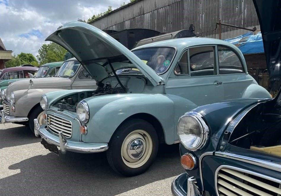
Let me preface all of what follows and say that I claim no credit whatsoever for most of the technical detail involved in the installation of a hazard flasher system on my ’62 DP Minor saloon. I did seek quite a bit of advice and reassurance from the MMOC on-line forum.
I make this point specifically, to assure anyone without a degree in auto-electrics, that they can takle this job with confidence if you are methodical and take your time.
There were a couple of little bumps along the way but that is to be expected. Before the detail however, the obligatory safety notice: Don’t even think about starting until you have disconnected the battery!
What you need:-
- A 6 wire Combined Hazard Flasher switch with own relay and warning lamp.
- 2 mtres green 8.75amp cable (1 mtre will possibly suffice but at 53p per mtre!)
- 2 mtres green/white 8.75amp cable (…………………………..ditto………………………………)
- Selection of bullet connectors and fasteners
- 2 x 6A10 Diodes
- Soldering iron
- A wiring diagram for reference – ideally from a workshop manual.
- Fire extinguisher (ONLY JOKING!)
What’s the plan Stan?
Basically, follow this simple wiring diagram:-

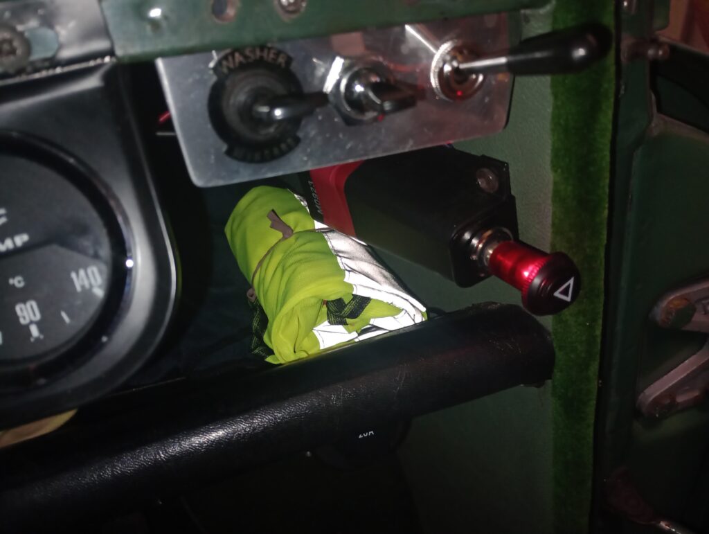
- Decide on a location for the Hazard Flasher switch. I mounted it on the offside side panel between the dash and the parcel shelf – secured by 2 self-tappers into holes drilled into the inner ‘A’ post.
No need to fully secure at this stage. It’s just to work out length of cables, access etc. Mounting here, enables the HF green/brown wires to connect directly to the ignition/indicator switch wire without the need for extensions.
- Remove the offside glove compartment. It is possible with the steering wheel in place……but it’s a bit like separating those metal loops you get in Christmas crackers. Just at the right angle and with a bit of compression and it comes through the wheel.
Top Tip: Remember how you got it out, ‘cos it’s got to go back in the same way!
- Following the diagram: Find the green/brown cable from the ignition switch which leads, via a multiple bullet connector, (where it becomes a solid green wire) to the indicator stalk. Remove ignition side g/b wire from the multiple bullet and connect it to one of the green/brown wires from the HF.
- Connect the other g/b wire from the HF to the multi-bullet connector you just removed the ‘loom’ g/b wire from.
- Extend the HF green wire through a grommetted hole in the bulkhead and on to terminal 6 of the DB10 relay.
- Same as above, with the green/white wire, to terminal 2.
- Connect black wire from the HF to a good clean earth.
- Connect the HF purple wire (which had a built-in in-line fuse) to a permanent live (i.e. non-ignition switched) source. Something from A2 of the fuse box or, as in my case, I ‘piggy-backed’ off a perm live feed to a cigarette lighter.
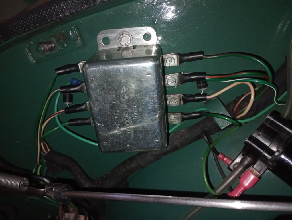
- At the DB10, under the bonnet, I used small ring connectors to seccure the green & green/white wires to their respective terminals. With the screw passing through the ring, it keeps it in place whilst also trying to slide on the existing ‘fork’ connectors (of the wires which feed both front indicators) AND one end of the diode.
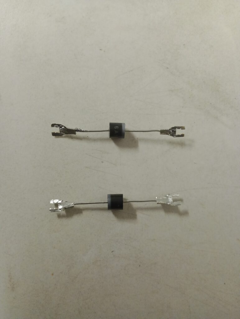
- It was a bit fiddly trying to fit the diode ‘as is’ between terminals 2 & 3 an 6 & 7 on the DB10, so I ‘modified’ some tiny speaker wire female connectors to make a crude but effective fork connector for each end of the diodes. Making them as flat as possible and with a dab of solder, the forked ends of the diodes slid easily under the existing connectors for a nice neat and secure job.
What is a diode and what does it do?
In essence, it’s a one-way electrical valve. It allows current to flow one way only.
Note: The current needs to flow from terminals 2 and 6 (both front indicators) to 3 and 7 (both rear indicators) respectively. The direction of travel is not actually marked on a diode (that would be far too easy!!) but they are all marked with a narrow band at one end and it is towards that band that the current travels.
The narrow bands for this installation need to be closer to terminals 3 and 7.
Why are diodes needed at all?
If there were direct connections between the terminals which activate the front and rear sidelights (i.e. without diodes) the hazard flasher would still work BUT applying the brake lights would also operate the front sidelights. Not recommended!
What could possibly go wrong?
Having connected everything up and reconnected the battery, the HF switch only illuminated the front sidelights and they didn’t flash either. Some head scratching and 48 hours later I had a ‘lightbulb’ moment……..well, more of an ‘LED’ moment actually! It dawned on me that I would need an electronic relay flasher unit and not the standard bi-metal relay. With LEDs all round on my car, they are drawing insufficient current to operate the normal flasher.
Within 30 minutes of my shiny new 2-terminal electronic flasher dropping through the letterbox, I had my hazard flashers working properly. Surprisingly, the electronic unit was slightly larger than the bi-metal one I replaced it with, so I had to modify the bracket on the HF switch assembly to accommodate the new relay before I could finally mount it on the side panel.
ET VOILÀ……….
For reference, these are the symbols typically found on a flasher relay:-
X or B = Power L = Load out (i.e. to the lights) P = Pilot light E = Earth
I do hope I’m not tempting fate by fitting hazard flashers! I’ve limped home a couple of times but never actually broken down by the roadside. There are no plans for extensive motorway journeys either but what H F will do, is give me a bit more confidence that if I do happen to breakdown in an awkward spot on a busy road, I and any passengers have got a fighting chance of getting out of the car quickly and safely. I don’t intend to use them as ‘park anywhere I like‘ lights!

Leave a Reply